logo
Supal (Changzhou) Precision Tools Co.,Ltd
อ้าง
เกี่ยวกับเรา
พาร์ทเนอร์มืออาชีพและน่าเชื่อถือของคุณ
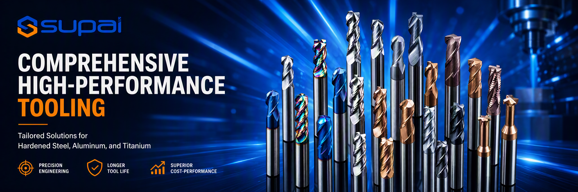
Supal (Changzhou) Precision Tools Co., Ltd. ได้ดำเนินธุรกิจด้านการออกแบบ ผลิต และจำหน่ายเครื่องมือคาร์ไบด์แข็งมาเป็นเวลาหลายปี ด้วยเงินลงทุนรวมกว่า 10 ล้านหยวน และประกอบด้วยกลุ่มพนักงานที่มีประสบการณ์ในฐานะผู้ผลิตเครื่องมือระดับมืออาชีพ บริษัทฯ ได้กลายเป็นหนึ่งในสมาชิกกรรมการของสมาคมเครื่องมือ Changzhou Xiaxiashu บริษัทฯ ได้นำเข้าเครื่องจักรจาก Walter และ Schutte ของเยอรมนี, ANCA ของออสเตรเลีย และเครื่องเจียร NC ห้าแกน นอกจากนี้ บริษัทยังติดตั้งเครื่องตรวจจับอัตโนมัติสำหรับเครื่องมือตัดของ ...
เรียนรู้ เพิ่มเติม

0

ปีที่ก่อตั้ง:

0

ล้าน+
พนักงาน

0

ล้าน+
ยอดขายประจำปี:
จีน Supal (Changzhou) Precision Tools Co.,Ltd คุณภาพสูง
พิมพ์ความไว้วางใจ ตรวจสอบเครดิต RoSH และการประเมินความสามารถของผู้จําหน่าย บริษัทมีระบบควบคุมคุณภาพอย่างเข้มงวด และห้องทดสอบมืออาชีพ
จีน Supal (Changzhou) Precision Tools Co.,Ltd การพัฒนา
ทีมงานออกแบบเชี่ยวชาญภายใน และโรงงานเครื่องจักรที่ทันสมัย เราสามารถร่วมมือกัน เพื่อพัฒนาสินค้าที่คุณต้องการ
จีน Supal (Changzhou) Precision Tools Co.,Ltd การผลิต
เครื่องจักรอัตโนมัติที่ทันสมัย ระบบควบคุมกระบวนการอย่างเข้มงวด เราสามารถผลิตเทอร์มินัลไฟฟ้าได้มากกว่าที่คุณต้องการ
จีน Supal (Changzhou) Precision Tools Co.,Ltd บริการ 100%
ขนของจํานวนมากและบรรจุของขนาดเล็กตามความต้องการ FOB, CIF, DDU และ DDP ขอให้เราช่วยคุณหาทางแก้ปัญหาที่ดีที่สุด

คุณภาพ เครื่องมือบดคาร์ไบด์ & เครื่องบดปลายสี่เหลี่ยม ผู้ผลิต

ค้นหาผลิตภัณฑ์ที่ตอบสนองความต้องการของคุณได้ดีขึ้น
อุปกรณ์ที่กําหนดเอง EVA Foam Deck Carbide Video

อุปกรณ์ที่กําหนดเอง EVA Foam Deck Carbide

หา ราคา ที่ ดี ที่สุด
กรณีและข่าว
จุดร้อนล่าสุด
Corner Radius vs Square End Mills for Interrupted Shoulder Milling
Corner Radius vs Square End Mills for Interrupted Shoulder Milling Interrupted shoulder milling is one of the operations where end mill geometry has a direct effect on edge stability. When the cutter repeatedly enters and exits the workpiece, passes across gaps, or encounters uneven stock, each tooth experiences a changing load instead of a smooth continuous cut. A square end mill can produce a sharp 90-degree shoulder, while a corner radius end mill can distribute load around the tool corner and reduce local stress. Choosing between them requires more than looking at the drawing requirement. For CNC machinists, process engineers, and purchasing engineers, the correct decision depends on the balance between required corner definition, interruption severity, tool rigidity, material, engagement, and finishing strategy. This guide compares square and corner-radius geometries for interrupted shoulder milling and explains how to diagnose edge chipping, chatter, poor finish, and unstable tool life. What Makes Interrupted Shoulder Milling Difficult? In a continuous side-milling cut, the cutting edge enters the workpiece and remains engaged in a relatively predictable way. In an interrupted shoulder operation, the edge may encounter a slot, a cross-hole, a casting irregularity, a forged surface, a previous pocket, or an open boundary. Each interruption changes the force and can create impact at entry or exit. The highest-risk conditions usually include: Repeated entry and exit at the same corner of the tool Full radial engagement at a 90-degree shoulder Thin walls or weak workholding that move during the cut Long tool overhang or poor holder runout Abrasive scale, cast skin, or hard inclusions Excessive feed or engagement at the interruption point A sharp square corner exposed to repeated impact A tool can therefore fail even when the average cutting load appears acceptable. The peak impact load, not only the average spindle load, may determine whether the edge survives. Square End Mills: Strengths and Limits A Square End Mill is the natural choice when the part requires a sharp internal shoulder or a flat-bottomed slot. Its geometry can produce a defined 90-degree corner without leaving a programmed radius at the bottom of the wall. When a Square End Mill Is Appropriate Square end mills are often considered when: The finished feature requires a sharp shoulder The toolpath uses stable, continuous engagement The workpiece and fixture are rigid The interruption is limited or can be approached with a controlled entry A separate finishing pass can protect the final corner quality The tool diameter and reach provide sufficient core strength A square tool can perform well in interrupted milling when the edge is properly supported and the engagement is controlled. It should not be rejected simply because the cut is interrupted; the severity and location of the interruption matter. Where Square Corners Become Vulnerable The tool corner is a stress concentration. During an interrupted cut, the corner may take a sudden impact as it enters the material. If the tool is also deflecting, the corner can receive more load than the other flutes. Typical results include corner chipping, a small radius appearing on the part after wear, chatter marks, or an abrupt change in surface finish. A sharp corner can also be sensitive to hard spots, scale, and thin-wall movement. If the failure is concentrated at the corner while the side cutting edges remain relatively intact, geometry and engagement should be reviewed before changing coating alone. Corner Radius End Mills: Strengths and Limits A Corner Radius End Mill includes a controlled radius between the end face and peripheral cutting edge. The radius removes the most fragile sharp corner and distributes cutting load over a larger region of the tool tip. When a Corner Radius Is Advantageous A corner-radius tool is often considered when: The cut includes repeated entry and exit The operation encounters an interrupted or uneven surface Edge chipping is concentrated at a square corner The part drawing permits a small internal radius The operation uses higher engagement or heavier roughing The process needs additional corner strength and more stable tool life The radius does not eliminate vibration or poor setup conditions, but it can reduce the severity of a localized corner impact. It may also improve the tool’s tolerance of intermittent engagement when compared with an otherwise similar sharp-corner tool. The Geometric Trade-Off The main limitation is straightforward: a corner radius leaves a radius on the finished shoulder. If the part requires a sharp 90-degree internal corner, the radius may need to be removed by a secondary operation or replaced by a square finishing tool. A corner radius can also change the effective engagement and contact area. It should be evaluated together with axial depth, radial engagement, tool diameter, and the required surface finish rather than selected based on radius size alone. How to Choose Between the Two Geometries Start With the Drawing Requirement First identify whether a sharp internal corner is functionally required or simply shown as a nominal feature. If a small radius is acceptable, a corner-radius tool may provide a more robust roughing or semi-finishing process. If a sharp corner is essential, use a square tool where practical or plan a roughing-and-finishing sequence that controls the load on the final square edge. Identify the Interruption Type Not all interruptions have the same effect. A predictable open boundary may be easier to manage than a hard casting skin or an irregular forged surface. Cross-holes and slots can create repeated impact at a known location, while uneven stock can make the load unpredictable. Record where the first damage occurs. If chipping starts at every entry point, the issue may be impact or lead-in strategy. If it appears only at a particular section of the workpiece, inspect material condition and support at that location. Match the Tool to the Operation For roughing and semi-finishing, the added corner support of a radius can be valuable when the operation is interrupted. For finishing, a square tool may be preferred if the corner specification requires it and the setup can maintain stable engagement. A practical process may use a corner-radius tool for stock removal, followed by a square end mill for the final shoulder. The two tools should not automatically use identical cutting conditions; the finishing tool may require a different engagement and a more controlled pass. Geometry, Edge Preparation, and Coating Edge Preparation A completely sharp edge may reduce cutting force in some materials, but it can be vulnerable to impact. A lightly reinforced edge may provide better stability in interrupted cuts, although excessive edge honing can increase rubbing and heat. The appropriate edge preparation depends on the workpiece, interruption severity, tool diameter, and operation. When comparing tools, request information about edge preparation rather than evaluating only flute count or coating name. Two tools with similar descriptions may behave differently if their edge preparation and carbide substrate differ. Helix and Flute Configuration Helix and flute count influence force direction, chip evacuation, and the number of teeth sharing the load. A higher flute count may support feed capacity in a light radial finishing pass, while a roughing or interrupted operation may need more chip space and a stronger core. The right balance depends on the material and engagement. A tool with insufficient flute space may recut chips, while a tool with a very thin core may lack impact resistance. Select from the broader Carbide Milling Tools range based on the actual operation rather than relying on the end mill shape alone. Coating Coating should follow the dominant failure mechanism. A coating may help manage heat, adhesion, or abrasive wear, but it cannot compensate for excessive tool deflection, a sharp corner overloaded by impact, or an unstable fixture. If the tool chips at entry, check geometry and rigidity before assuming that a coating change is the primary solution. Any coating recommendation should be validated with the specific material, tool geometry, coolant strategy, and cutting conditions. Treat supplier data as a starting reference and confirm the result on the actual machine. Parameter Strategy for Interrupted Shoulder Milling Cutting data should be treated as a starting reference for the exact diameter, flute count, coating, material grade, tool overhang, and machine setup. Do not transfer a value from a continuous side-milling operation directly to an interrupted shoulder cut without validation. Control the Peak Load at Entry Entry conditions can create the highest impact. Where the geometry allows, use a ramp, arc, or controlled lead-in instead of an abrupt radial plunge. This reduces the sudden change from no load to full engagement. If a direct entry is unavoidable, review feed and radial engagement at the entry point. A controlled reduction in engagement or a separate approach pass may protect the edge better than reducing the entire program feed. Avoid Excessive Full-Width Engagement Full-width shoulder milling creates significant radial load. In an interrupted condition, the load can change sharply as the tool crosses the gap. If possible, use a reduced radial engagement strategy for roughing and leave a controlled allowance for finishing. The correct engagement depends on the tool, material, machine, and feature geometry. Validate changes with spindle load, sound, chip form, and edge inspection rather than assuming that a smaller engagement is always better. Adjust Speed and Feed One Variable at a Time If the tool chips, do not immediately reduce both speed and feed. First determine whether the damage is impact-related, vibration-related, or caused by rubbing. A feed reduction that is too large can create a thin chip and increase rubbing, while a speed change may affect heat and resonance differently. Change one parameter at a time and document the effect. Include the location of the failure, chip appearance, surface finish, and tool condition in the record. Diagnosing Common Failure Symptoms Corner Chipping on a Square End Mill Check interruption severity, tool entry, runout, edge preparation, and whether the square corner is taking the full impact. If the drawing permits it, compare a corner-radius tool in the roughing or semi-finishing stage. If a square corner is mandatory, reduce entry shock and ensure the finishing pass has consistent stock. Chatter on a Corner-Radius Tool A radius does not remove the need for rigidity. Check tool overhang, holder condition, workholding, spindle speed, axial depth, and radial engagement. Chatter may also result from a radius that creates an engagement pattern unsuitable for the current toolpath. Uneven Wear Between Flutes Uneven wear commonly points to runout, unequal flute loading, poor holder seating, or a workpiece that is moving. Inspect the shank, collet, holder, and setup before changing the tool geometry. Poor Shoulder Finish After Roughing A roughing tool with a damaged corner or built-up edge should not be used for a critical finishing pass. Clean the feature, use a sound finishing tool, and verify that the remaining allowance is consistent. If the finish still varies, inspect vibration and workholding. Short Tool Life at a Hard Spot If damage occurs only at a particular location, investigate material condition, scale, interrupted geometry, or inadequate support. A different corner geometry may help, but the toolpath and entry strategy should also be reviewed. Common Mistakes to Avoid Choosing a Square Tool Only Because the Part Has a 90-Degree Corner A square finishing tool may be correct for the final feature but unnecessarily vulnerable during heavy interrupted roughing. Separate stock removal from final corner generation when the process requires both robustness and a sharp corner. Assuming a Corner Radius Always Solves Chipping The radius can improve corner strength, but it does not fix excessive overhang, runout, unstable workholding, poor parameters, or a damaged holder. Reducing Feed Aggressively After Chipping A large feed reduction can cause rubbing and heat. Determine whether the first damage occurred at entry, during an interruption, or under continuous cutting before making broad changes. Ignoring Toolholding The geometry selected on paper cannot compensate for poor holder cleanliness, excessive runout, or unnecessary projection. Check the actual holder and machine setup. Mixing Roughing and Finishing Requirements One tool rarely provides the best combination of high interruption tolerance, high stock-removal capacity, sharp 90-degree finishing, and final surface quality. Define which pass is responsible for each requirement. FAQ Is a corner radius end mill stronger than a square end mill? The radius removes the sharpest corner stress concentration and can improve resistance to local chipping in some interrupted operations. The actual result still depends on material, edge preparation, tool diameter, engagement, rigidity, and parameters. Should I use a corner radius for every interrupted shoulder cut? No. If a sharp 90-degree corner is required, a square end mill may still be necessary for finishing. A corner-radius tool can be considered for roughing or semi-finishing when the part permits a radius or a secondary finishing operation. Why does my square end mill chip only at the entry point? The entry may create an impact or engagement spike. Check lead-in strategy, radial engagement, feed at entry, runout, workpiece support, and the condition of the material surface at the entry location. Can changing the coating stop corner chipping? Only when the dominant failure involves heat, adhesion, or wear that the new coating is suited to control. Coating cannot correct an overloaded corner, poor rigidity, abrupt entry, or excessive engagement. What information should I provide when requesting an end mill recommendation? Provide the material grade, shoulder and interruption geometry, required corner condition, tool diameter and reach, machine and holder details, current parameters, coolant method, tool wear pattern, and photographs of the damaged edge or finished shoulder. Conclusion The choice between a corner-radius and square end mill for interrupted shoulder milling should begin with the part requirement, then consider interruption severity, edge strength, tool rigidity, engagement, and finishing strategy. A square end mill provides a sharp corner but concentrates stress at the tool tip. A corner-radius end mill distributes load more gradually and may reduce local chipping when a radius is acceptable. For demanding operations, a two-stage process can balance both objectives: use a robust geometry for interrupted roughing or semi-finishing, then use a square tool for the final shoulder when the drawing requires a sharp corner. Build parameters from the supplier’s starting range, change one variable at a time, and validate the complete process on the actual machine and workholding. If your shoulder milling process shows corner chipping, chatter, poor finish, or inconsistent tool life, Contact Supal with the material grade, interruption geometry, current tool, tool overhang, parameters, and photos of the failure. This information helps identify a practical geometry and process starting point for on-machine validation.

2026

10/06

How to Choose Carbide End Mills for Copper and Brass Machining
How to Choose Carbide End Mills for Copper and Brass Machining Copper, brass, bronze, and other copper alloys are often described as easy-to-cut materials because they are softer than hardened steel. That description can be misleading. Copper alloys can create very different machining problems depending on their purity, temper, alloying elements, work-hardening behavior, and chip form. A tool that produces a clean result in free-machining brass may rub, smear, or generate built-up edge in a more adhesive copper grade. For CNC machinists, process engineers, and purchasing engineers, reliable copper alloy milling starts with matching the tool to the actual failure mechanism. Edge sharpness, flute space, chip evacuation, workholding, coolant, and parameter validation usually matter more than simply choosing the hardest or most expensive coating. This guide explains how to select carbide end mills for copper and brass machining while reducing adhesion, burrs, heat, and unstable tool life. Why Copper and Brass Need Material-Specific Tool Selection Copper alloys combine several characteristics that influence milling stability: Copper conducts heat efficiently, so heat can move into the workpiece instead of remaining concentrated at the tool edge. However, local rubbing can still raise edge temperature and cause adhesion. Pure or highly ductile copper can produce continuous, gummy chips that are difficult to evacuate. Brass and bronze grades vary widely. Some produce short chips, while others create longer chips or abrasive particles. A dull edge may rub and smear the surface rather than shear it cleanly. Thin walls, small features, and poor workholding can amplify deflection and burr formation. The result is that “copper” or “brass” is not enough information for final tool selection. The exact alloy or grade, hardness or temper condition, feature geometry, and finishing requirement should be confirmed before adopting a production tool. Common Failure Symptoms in Copper Alloy Milling Built-Up Edge and Material Adhesion Built-up edge appears when copper or another ductile alloy adheres to the cutting edge. The tool may look sharp at the beginning of the cut but gradually develops a welded mass that changes the effective edge geometry. This can cause poor surface finish, burrs, dimensional variation, and sudden edge damage when the built-up material breaks away. Adhesion is often promoted by rubbing, insufficient chip evacuation, a dull edge, excessive dwell, or a surface treatment that is not suited to the material. Changing to a harder coating without correcting rubbing may not solve the problem. Smearing and Poor Surface Finish A smeared surface usually indicates that the tool is not shearing the material cleanly. Possible causes include insufficient chip thickness, a dull or heavily honed edge, poor tool runout, unstable workholding, or a speed/feed combination that leaves the tool rubbing instead of cutting. Burrs at Entry and Exit Copper and brass can produce burrs when the cutting edge pushes material away at the exit. Burr formation is influenced by tool sharpness, radial engagement, feed direction, workpiece support, and the condition of the edge. A finishing pass may reduce burrs, but the root cause should still be addressed in the toolpath and tool selection. Chipped Edge or Unexpected Tool Failure Carbide edge chipping in copper alloy milling is not always caused by a material that is too hard. Interrupted cuts, loose workholding, excessive runout, thin-wall deflection, collisions, and trapped chips can generate impact loads that damage the edge. If chipping is concentrated on one flute, inspect runout and setup balance before changing the carbide grade. Chip Packing and Recutting Long copper chips can remain in a pocket, slot, or narrow cavity. Once recut, they create additional heat and load, increasing the chance of built-up edge and surface scratching. Tool geometry and air or coolant direction should be selected with chip travel in mind, especially in deep features. Flute Geometry and Edge Sharpness Choose Enough Chip Space for the Operation Copper and ductile brass grades may require generous flute space so chips can leave the cutting zone before they are recut. A low-flute-count tool can be useful when chip evacuation is the primary limitation, but the correct flute count also depends on rigidity, engagement, feed, finish, and feature geometry. For a deep pocket or slot, prioritize a toolpath and geometry that provide a clear chip path. For a light finishing pass, a different flute configuration may be preferred if it provides the required surface quality without creating excess rubbing. Favor a Clean, Sharp Cutting Edge A sharp edge generally helps shear copper and brass rather than push or smear them. Excessive edge rounding can increase rubbing and heat. However, sharpness must be balanced against the risk of edge damage in interrupted cuts, cast surfaces, abrasive inclusions, or unstable fixtures. The best edge preparation is application-dependent. A stable finishing cut may benefit from a very sharp edge, while a roughing operation with impact risk may require controlled edge reinforcement. Request the intended edge preparation when comparing tools rather than judging only by the product title. Consider Polished Flutes and Rake Surfaces A smooth flute and rake surface can reduce friction and help chips slide away from the cutting edge. This is particularly relevant when the material tends to adhere or when the tool is used in a narrow cavity with limited chip clearance. Polishing alone does not replace the need for suitable flute volume, coolant, or air blast, but it can support cleaner chip transport. Coating and Substrate Considerations Copper alloy applications do not always benefit from the same coating choices used for hardened steel. The dominant issue may be adhesion and friction rather than oxidation or high-temperature wear. In some applications, uncoated polished carbide is appropriate because the sharp, low-friction surface is more important than a hard coating layer. For abrasive copper alloys, bronze grades, or materials containing hard particles, a coating or substrate selected for wear resistance may be useful. The correct choice depends on the exact alloy and failure mode. Do not assume that a coating marketed for hardened steel will automatically improve copper machining, and do not assume that an uncoated tool is correct for every bronze or filled alloy. When comparing copper tools with End Mills for Aluminum, use the aluminum tool as a reference only, not as an automatic substitute. Both material groups can be adhesion-prone, but the exact chip form, edge condition, and surface requirement may differ. Parameter Strategy for Copper and Brass Milling Start With the Actual Tool and Alloy Cutting data should be treated as a starting reference, not a guaranteed setting. The appropriate speed, feed, radial engagement, and axial depth depend on tool diameter, flute count, stickout, machine rigidity, workholding, alloy grade, and coolant or air-blast conditions. Validate the starting range on the actual machine before making it a standard process. Avoid Rubbing and Dwell If the tool spends too much time sliding along the surface, adhesion and smearing become more likely. Check whether the toolpath includes dwell at corners, excessive radial engagement, or a feed value that is too low for the selected edge geometry. A modest, controlled chip load is usually preferable to a cut dominated by rubbing, but the exact value must be validated for the tool and material. Control Chip Evacuation Direct air or coolant so chips move away from the cutting zone rather than being pushed back into the pocket. If chips are long, review flute volume, toolpath engagement, and the conditions that determine chip formation. Increasing fluid pressure without correcting nozzle direction or chip path may produce little improvement. Change One Variable at a Time When troubleshooting built-up edge, burrs, or poor finish, change only one major variable at a time: tool geometry, coating, speed, feed, engagement, or chip evacuation. Document the result. This makes it possible to identify the actual improvement instead of attributing every change to the last tool purchased. Toolholding, Workholding, and Feature Stability Even a well-selected tool can fail when the setup is unstable. Check tool runout, holder cleanliness, clamping length, and the shortest practical tool projection. Thin copper components and unsupported walls can deflect under cutting pressure, leaving burrs or dimensional error that look like a tool problem. For holes and finishing operations, coordinate the milling process with Carbide Drills and Carbide Reamers. A poor pre-hole or unstable entry can reduce the performance of the finishing tool even when the reamer itself is suitable. A Practical Selection and Troubleshooting Sequence Confirm the exact copper, brass, bronze, or copper-alloy grade and condition. Identify the dominant failure: adhesion, burrs, poor finish, chip packing, chipping, or dimensional drift. Select flute count and chip space based on engagement and chip travel, not on flute count alone. Review edge sharpness, rake surface, flute polish, coating, and substrate together. Check runout, overhang, workholding, and thin-wall support. Establish a conservative starting process and validate it on the actual setup. Adjust one variable at a time and record chip form, finish, burr condition, load behavior, and tool wear. Common Mistakes to Avoid Treating All Copper Alloys as Pure Copper Brass, bronze, and specialized copper alloys can produce very different chips and wear mechanisms. A recommendation for one grade should not be transferred automatically to another. Choosing Coating Before Identifying the Failure Mode If adhesion is the primary issue, friction and edge sharpness may deserve attention before thermal coating performance. If abrasion is dominant, the solution may require a different substrate or wear-resistant coating. Diagnose first. Using a Dull Tool for a Finishing Operation A worn edge can rub, smear, and create burrs even when the tool still appears usable. Replace or recondition the tool based on the required surface and dimensional result, not only on visible fracture. Ignoring Chip Travel in Pockets and Slots Long chips that remain in the cavity will be recut. Review toolpath direction, flute space, air blast, coolant placement, and the ability of the machine to clear chips. Copying Parameters From Steel or Aluminum Without Validation Copper alloy behavior is not identical to steel or aluminum. Use supplier data as a starting reference and confirm the process on the actual machine, workholding, and material grade. FAQ What type of carbide end mill is commonly used for copper? A sharp, low-friction tool with suitable chip space is often considered for copper, but the correct flute count, edge preparation, coating, and substrate depend on the exact alloy and operation. Confirm the choice against the material grade and feature geometry. Why does copper create built-up edge on the tool? Built-up edge is commonly associated with adhesion, rubbing, heat concentration, poor chip evacuation, or an edge condition that is not suited to the material. Review sharpness, flute polish, toolpath engagement, and validated parameters before changing coating alone. Is an uncoated carbide end mill suitable for brass and copper alloys? It can be suitable in some applications where a sharp, polished, low-friction edge is the priority. Abrasive bronze or filled copper alloys may require a different wear strategy. The exact recommendation should be confirmed for the specific grade and failure mode. How can I reduce burrs when milling copper? Check tool sharpness, runout, exit engagement, workpiece support, radial engagement, and feed direction. A finishing pass may help, but burr reduction is usually more reliable when the edge and toolpath are stable from the beginning. What information should I provide when requesting a copper alloy tool recommendation? Provide the exact alloy and condition, tool diameter and flute count, feature geometry, tool overhang, machine and holder details, current parameters, coolant or air-blast method, chip form, and photographs of the finish or worn edge. Conclusion Choosing carbide end mills for copper and brass machining requires more than selecting a standard tool for a soft material. The best starting point is to identify the alloy, failure mode, chip behavior, and setup stability. Sharp and suitable geometry, sufficient chip space, controlled friction, reliable evacuation, and validated parameters work together to reduce built-up edge, burrs, smearing, chipping, and inconsistent tool life. If your copper or brass operation has adhesion, burr, chip evacuation, surface-finish, or tool-life problems, Contact Supal with the material grade, feature geometry, current tool, parameters, and failure photos. This information helps evaluate a practical tool and process starting point for on-machine validation.

2026

10/01

การสั่นสะเทือนของรีมเมอร์คาร์ไบด์และรูที่ใหญ่เกินขนาด: คู่มือการแก้ไขปัญหา
ดอกรีมเมอร์คาร์ไบด์มีเสียงพูดคุยและรูขนาดใหญ่: คู่มือการแก้ไขปัญหา การรีมมักถือเป็นการดำเนินการเก็บผิวละเอียดแบบง่ายๆ นั่นคือ เจาะรู รันรีมเมอร์ และคาดว่าขนาดและผิวสำเร็จจะดีขึ้น ในทางปฏิบัติ การรีมคาร์ไบด์จะไวต่อค่าเผื่อ การปรับแนว ความแข็งแกร่ง การส่งน้ำหล่อเย็น รูปทรงของคมตัด และความเสถียรของพารามิเตอร์ เมื่อตัวแปรใดๆ เหล่านี้ผิดพลาด กระบวนการอาจทำให้เกิดรอยสะท้าน รูขนาดใหญ่เกินไป ความกลมไม่ดี รูเรียว การกะเทาะที่ขอบ หรืออายุการใช้งานเครื่องมือสั้นลงอย่างไม่คาดคิด สำหรับช่างเครื่อง CNC วิศวกรกระบวนการ และวิศวกรจัดซื้อ ประเด็นสำคัญคือ: รีมเมอร์ไม่ได้แก้ไขปัญหาการเจาะทุกปัญหา รีมเมอร์สามารถปรับปรุงรูที่เตรียมไว้ได้ แต่ไม่สามารถแก้ไขรูพรีรูที่ไม่ตรงแนวอย่างรุนแรง มีรอยขีดข่วน มีขนาดเล็กกว่า ปากระฆัง หรือไม่มั่นคงได้อย่างน่าเชื่อถือ คู่มือนี้จะอธิบายวิธีวินิจฉัยปัญหาการพูดคุยของรีมเมอร์คาร์ไบด์และความทนทานของรูทีละขั้นตอน ดังนั้น การดำเนินการแก้ไขจะขึ้นอยู่กับโหมดความล้มเหลว แทนที่จะใช้การคาดเดา เหตุใดปัญหาการรีมจึงวินิจฉัยได้ยาก ดอกรีมเมอร์คาร์ไบด์ตัดด้วยฟันหลายซี่ในคราวเดียว และขจัดวัสดุได้เพียงเล็กน้อยเท่านั้น เนื่องจากการดำเนินการมีน้ำหนักเบาเมื่อเทียบกับการเจาะหรือการกัด ร้านค้าหลายแห่งจึงคิดว่าการรีมควรให้ผลดี ในความเป็นจริง การเผื่อสต็อกไว้เล็กน้อยและเป้าหมายการยอมรับที่เข้มงวดทำให้กระบวนการให้อภัยน้อยลง หากค่าเผื่อการรีมน้อยเกินไป เครื่องมืออาจเสียดสีแทนการตัด หากค่าเผื่อมากเกินไป คมตัดอาจรับน้ำหนักมากเกินไปได้ หากรูที่เจาะไม่ตรง รีมเมอร์อาจเป็นไปตามข้อผิดพลาดที่มีอยู่หรือถูกบังคับให้ตัดไม่สม่ำเสมอ หากตัวยึดหรือฟิกซ์เจอร์ขาดความแข็งแกร่ง การสั่นสะเทือนเล็กน้อยอาจปรากฏเป็นเส้นสะท้านที่มองเห็นได้ภายในรู นี่คือสาเหตุที่รีมเมอร์ตัวเดียวกันอาจให้ผิวสำเร็จที่ดีเยี่ยมในการตั้งค่าครั้งเดียว และล้มเหลวในการตั้งค่าอื่นที่มีเส้นผ่านศูนย์กลางรูระบุเท่ากัน อาการทั่วไปของการรีมคาร์ไบด์ พูดพล่อยเครื่องหมายภายในหลุม เครื่องหมายพูดพล่อยมักจะปรากฏเป็นลวดลายเกลียวหรือรูปหลายเหลี่ยมซ้ำๆ บนผนังหลุม บ่งชี้ว่าเครื่องมือ ด้ามจับ ชิ้นงาน หรือโครงสร้างของเครื่องจักรเกิดการสั่นสะเทือนระหว่างการตัด การพูดคุยอาจเกิดจากการเผื่อไว้มากเกินไป ความแกร่งไม่เพียงพอ การตั้งศูนย์ที่ไม่ดี ความเร็วที่ไม่ถูกต้อง หรือพรีรูลที่ไม่เสถียร รูขนาดใหญ่หลังจากการรีม รูขนาดใหญ่เกินไปอาจเกิดจากการเบี่ยงเบนหนีศูนย์ของเครื่องมือ การวางแนวที่ไม่ถูกต้อง แรงกดในการตัดที่มากเกินไป การขยายตัวจากความร้อน หรือเศษที่ติดอยู่ระหว่างรีมเมอร์และผนังรู หากรูขนาดใหญ่เกินเกิดซ้ำๆ กัน ให้วัดความเบี่ยงเบนหนีศูนย์และตรวจสอบสภาพของรูเจาะก่อนจะถือว่าเส้นผ่านศูนย์กลางของรีมเมอร์ไม่ถูกต้อง พื้นผิวไม่ดี ผิวสำเร็จที่ไม่ดีหลังจากการรีมอาจมาจากการสะสมของคมตัด น้ำหล่อเย็นไม่เพียงพอ การตัดเศษ การเตรียมดอกสว่านที่ไม่ดี หรือคมตัดสึกหรอ เมื่อรีมเมอร์ถูกบังคับให้ขจัดเนื้อวัสดุที่ไม่สม่ำเสมอ ผิวสำเร็จมักจะแย่ลงแม้ว่าเครื่องมือจะคมก็ตาม อายุการใช้งานเครื่องมือสั้นหรือไม่สม่ำเสมอ หากรีมเมอร์ตัวหนึ่งมีอายุการใช้งานยาวนานกว่ารีมเมอร์ตัวอื่นในการใช้งานเดียวกัน ให้ตรวจสอบการตั้งค่าเครื่องจักร การเตรียมรู การจ่ายน้ำหล่อเย็น และความแปรผันของวัสดุชิ้นส่วน การเคลือบเครื่องมือและเกรดคาร์ไบด์ แต่ความไม่แน่นอนของกระบวนการมักเป็นสิ่งแรกที่ต้องกำจัด ขอบบิ่น การบิ่นที่ขอบบนรีมเมอร์คาร์ไบด์มักบ่งบอกถึงการกระแทก การตัดขาดระยะ ระยะเผื่อที่มากเกินไป การเข้าไปไม่ดี หรือมีการรวมตัวอย่างแข็งในชิ้นงาน รีมเมอร์เป็นเครื่องมือตกแต่งขั้นสุดท้าย ไม่ได้ออกแบบมาเพื่อแก้ไขข้อผิดพลาดในการเจาะขนาดใหญ่หรือกำจัดวัสดุที่มีน้ำหนักมาก สาเหตุที่ 1: ค่าเผื่อการรีมไม่ถูกต้อง ค่าเผื่อรูก่อนเป็นตัวแปรที่สำคัญที่สุดประการหนึ่งในการรีม ปริมาณสต๊อกที่น้อยเกินไปอาจทำให้เกิดการเสียดสี ความร้อน และคุณภาพงานไม่ดีได้ การมีสต็อกมากเกินไปอาจทำให้คมตัดรับน้ำหนักมากเกินไป และทำให้เกิดการสะท้านหรือบิ่นได้ ไม่มีค่าเผื่อสากลที่เหมาะกับทุกขนาดเส้นผ่านศูนย์กลาง วัสดุ และการออกแบบรีมเมอร์ ตามหลักการเริ่มต้น โดยทั่วไปแล้วรูที่มีเส้นผ่านศูนย์กลางเล็กจะต้องเผื่อเผื่อไว้น้อยกว่า ในขณะที่รูที่ใหญ่กว่าสามารถทนต่อการกำจัดเศษวัสดุได้มากกว่า อย่างไรก็ตาม ค่าที่ถูกต้องจะขึ้นอยู่กับวัสดุชิ้นงาน ความลึกของรู รูปทรงเครื่องมือ วิธีการจ่ายน้ำหล่อเย็น และเป้าหมายความคลาดเคลื่อน ตรวจสอบค่าเผื่อบนเครื่องจักรและฟิกซ์เจอร์จริงเสมอ แทนที่จะคัดลอกค่าจากการทำงานอื่น เมื่อแก้ไขปัญหา ให้เปรียบเทียบเส้นผ่านศูนย์กลางรูเจาะจริงก่อนทำการรีมกับชิ้นงานสุดท้าย หากขนาดรูเจาะล่วงหน้าแตกต่างกันไปในแต่ละชิ้นส่วน ผลการรีมก็จะแตกต่างกันไปด้วย สาเหตุที่ 2: คุณภาพหลุมก่อนรูต่ำ ดอกรีมเมอร์ต้องการตัวนำทางที่มั่นคง หากรูที่เจาะอยู่นอกตำแหน่ง เรียว มีรอยขีดข่วน หรือมีความแข็งมาก การรีมจะยากขึ้นมาก ก่อนจะตำหนิรีมเมอร์ควรตรวจสอบกระบวนการเจาะก่อน ตรวจสอบว่าสว่านทำให้เกิดรูกลมและเป็นรูตรง มีเศษเป็นรอยบนผนังหรือไม่ และสว่านกำลังเดินอยู่ที่ทางเข้าหรือไม่ สำหรับการควบคุมกระบวนการเจาะรูดอกสว่านคาร์ไบด์และควรเลือกรีมเมอร์เป็นระบบ ไม่ใช่เป็นเครื่องมือที่ไม่เกี่ยวข้องกัน หากดอกสว่านทำให้เกิดรอยขีดข่วนเศษอย่างรุนแรงหรือขนาดรูไม่สอดคล้องกัน รีมเมอร์อาจไม่สามารถควบคุมการซ่อมแซมข้อบกพร่องได้เพียงพอ ปรับปรุงความมั่นคงในการเจาะก่อน จากนั้นจึงประเมินรอบการรีม สาเหตุที่ 3: การหนีศูนย์และการวางแนวไม่ตรง การเบี่ยงเบนหนีศูนย์เป็นหนึ่งในวิธีที่เร็วที่สุดในการสร้างรูขนาดใหญ่และการสึกหรอของเครื่องมือไม่สม่ำเสมอ การเบี่ยงเบนหนีศูนย์เล็กน้อยที่ตัวจับยึดหรือสปินเดิลอาจทำให้คมตัดหนึ่งทำงานได้มากกว่าคมตัดอื่นๆ สิ่งนี้ทำให้เกิดแรงกดในการตัดไม่สม่ำเสมอ ความกลมไม่ดี และอายุการใช้งานเครื่องมือสั้นลง ตรวจสอบความหนีศูนย์ที่ด้ามเครื่องมือและใกล้กับส่วนตัดเมื่อเป็นไปได้ ตรวจสอบสภาพของตัวจับยึด ความสะอาดของปลอกรัด สภาพของสปินเดิล และตรวจสอบว่าเครื่องมือถูกยึดโดยมีความยาวหน้าสัมผัสเพียงพอหรือไม่ สำหรับรูเจาะที่แม่นยำ ระบบจับยึดเครื่องมือมีความสำคัญพอๆ กับตัวรีมเมอร์ การวางแนวที่ไม่ตรงอาจเกิดขึ้นได้เมื่อรีมเมอร์เข้าไปในรูที่ไม่อยู่โคแอกเซียลกับทางเดินของสปินเดิล นี่เป็นเรื่องปกติเมื่อการทำงาน การติดตั้ง หรือการตั้งค่าระยะไกลก่อนหน้านี้ทำให้เกิดการโก่งตัว สาเหตุที่ 4: ความเร็ว อัตราป้อน และความเสถียรในการตัด พารามิเตอร์การรีมควรมีความเสถียรเพียงพอที่จะตัดได้อย่างหมดจดโดยไม่ต้องเสียดสีหรือสั่นสะเทือน ความเร็วที่สูงเกินไปอาจทำให้ความร้อนเพิ่มขึ้นและทำให้วัสดุบางชนิดแย่ลงได้ การป้อนต่ำเกินไปอาจทำให้เกิดการเสียดสีมากกว่าการตัด การป้อนสูงเกินไปอาจทำให้ขอบรับภาระมากเกินไป และทำให้พื้นผิวสำเร็จเสียหายได้ สำหรับการแก้ไขปัญหา ให้ปรับตัวแปรทีละรายการ หากมีการพูดคุยเกิดขึ้น การลดความเร็วลงเล็กน้อยอาจช่วยได้ แต่เฉพาะในกรณีที่ความเข้มงวดและการเผื่อไว้นั้นสมเหตุสมผลแล้วเท่านั้น หากเครื่องมือเสียดสีและเกิดความร้อน การเพิ่มอัตราป้อนในช่วงที่ปลอดภัยในบางครั้งอาจช่วยปรับปรุงการตัดได้ การเปลี่ยนแปลงพารามิเตอร์ควรได้รับการตรวจสอบโดยการทดลองตัดวัสดุชิ้นส่วนจริง หลีกเลี่ยงการใช้ตารางความเร็วและฟีดทั่วไปเป็นค่าสุดท้าย ถือเป็นข้อมูลอ้างอิงเริ่มต้น และปรับตามขนาดรู ความลึก ความแข็งแกร่งของเครื่องจักร ระบบจ่ายน้ำหล่อเย็น และข้อกำหนดด้านความคลาดเคลื่อน สาเหตุที่ 5: การควบคุมน้ำหล่อเย็นและเศษ แม้ว่าการรีมจะใช้วัสดุน้อยกว่าการเจาะ แต่เศษยังคงมีความสำคัญ เศษหรืออนุภาคละเอียดที่ติดอยู่ภายในรูอาจทำให้ผนังเป็นรอยและทำให้คมตัดเสียหายได้ สารหล่อเย็นช่วยชะล้างเศษ ลดความร้อน และทำให้บริเวณการตัดมีความเสถียร สำหรับรูตัน การคายเศษจะยากขึ้นเนื่องจากเศษมีพื้นที่จำกัดที่จะออกจากด้านล่างของรู ควรตรวจสอบทิศทาง แรงดัน และการไหลของน้ำหล่อเย็นอย่างระมัดระวัง หากเศษยังคงอยู่ในรูจากการเจาะ ให้ทำความสะอาดหรือล้างรูก่อนทำการรีม ความเข้มข้นและการกรองของน้ำหล่อเย็นก็มีความสำคัญเช่นกัน สารหล่อเย็นที่ปนเปื้อนสามารถนำพาอนุภาคที่มีฤทธิ์กัดกร่อนกลับเข้าไปในรูได้ ซึ่งส่งผลต่อคุณภาพผิวงานและอายุการใช้งานของเครื่องมือ สาเหตุที่ 6: รูปทรงของรีมเมอร์และความพอดีในการใช้งาน แตกต่างรีมเมอร์คาร์ไบด์ได้รับการออกแบบมาเพื่อการใช้งานที่แตกต่างกัน ปัจจัยต่างๆ เช่น การออกแบบร่องมุม มุมนำ การออกแบบระยะขอบ การเตรียมคมตัด และการเคลือบ อาจส่งผลต่อความเสถียรในการตัดและการคายเศษ ดอกรีมเมอร์สำหรับรูทะลุอาจไม่ทำงานเหมือนกันในรูตัน รีมเมอร์ที่ปรับให้เหมาะกับอะลูมิเนียมอาจไม่เหมาะกับเหล็กสเตนเลสหรือวัสดุชุบแข็ง รีมเมอร์ขนาดยาวอาจต้องการความเอาใจใส่เป็นพิเศษในเรื่องความแข็งแกร่งและการเบี่ยงเบนหนีศูนย์ เมื่อหารือเกี่ยวกับปัญหาของรีมเมอร์กับซัพพลายเออร์ ให้จัดเตรียมวัสดุชิ้นงาน เส้นผ่านศูนย์กลางรูเจาะ ค่าเผื่อเป้าหมาย ความลึกของรู สภาพของรูทะลุหรือรูบอด วิธีการจ่ายน้ำหล่อเย็น พารามิเตอร์ปัจจุบัน และรูปถ่ายพื้นผิวของรู หากมี ข้อมูลนี้ช่วยพิจารณาว่าวิธีแก้ปัญหาคือการเปลี่ยนแปลงรูปทรง การเปลี่ยนแปลงพารามิเตอร์ หรือการแก้ไขกระบวนการ ขั้นตอนการแก้ไขปัญหาเชิงปฏิบัติ ขั้นตอนที่ 1: วัด Pre-Hole ก่อนตรวจสอบรูที่เสร็จแล้ว ให้วัดรูที่เจาะหรือรูเจาะก่อนทำการรีม บันทึกเส้นผ่านศูนย์กลาง ความกลม ความตรง หากเป็นไปได้ และสภาพพื้นผิว ถ้ารูปรีไม่มั่นคง ให้ซ่อมก่อน ขั้นตอนที่ 2: ตรวจสอบการวิ่งหนีของเครื่องมือ วัดความหนีศูนย์ในที่จับจริง ทำความสะอาดด้าม ปลอกรัด และที่จับ เปลี่ยนตัวยึดที่ชำรุดหรือปลอกรัดที่ชำรุด หากการเบี่ยงเบนหนีศูนย์ลดลงและรูขนาดใหญ่ขึ้นดีขึ้น แสดงว่ารีมเมอร์ไม่ใช่สาเหตุหลัก ขั้นตอนที่ 3: ตรวจสอบเบี้ยเลี้ยง เปรียบเทียบเส้นผ่านศูนย์กลางรูล่วงหน้าจริงกับขนาดรีมเมอร์ หากค่าเผื่อแตกต่างกันไปในแต่ละชิ้นส่วน ให้ระบุว่าเหตุใดการดำเนินการเจาะหรือการคว้านจึงไม่สอดคล้องกัน ขั้นตอนที่ 4: ตรวจสอบชิปและการตกแต่งพื้นผิว มองหาเศษที่ติดอยู่ในรู รอยขีดข่วน หรือรอยถู หากเศษมีรอยขีดข่วน ให้ปรับปรุงการชะล้างน้ำหล่อเย็นและการทำความสะอาดรูล่วงหน้า ขั้นตอนที่ 5: ปรับพารามิเตอร์ทีละน้อย เปลี่ยนความเร็ว อัตราป้อน หรือน้ำหล่อเย็นทีละปัจจัย บันทึกผลลัพธ์ หลีกเลี่ยงการเปลี่ยนรูปทรงและพารามิเตอร์ของเครื่องมือไปพร้อมๆ กัน เว้นแต่ว่าการตั้งค่าปัจจุบันไม่เหมาะสมอย่างชัดเจน ขั้นตอนที่ 6: ตรวจสอบการเลือกเครื่องมือ หากกระบวนการมีเสถียรภาพแต่ปัญหายังคงอยู่ ให้ตรวจสอบรูปทรงของรีมเมอร์ การเคลือบ รูปแบบร่อง และการเตรียมคมตัด สำหรับงานตัดเฉือนและการเก็บผิวละเอียดที่เกี่ยวข้อง Supal ก็มีให้เช่นกันเครื่องมือกัดคาร์ไบด์เพื่อการวางแผนกระบวนการ CNC ที่กว้างขึ้น ข้อผิดพลาดทั่วไปที่ควรหลีกเลี่ยง ข้อผิดพลาด 1: คาดว่ารีมเมอร์จะแก้ไขหลุมที่ไม่ดี รีมเมอร์เป็นเครื่องมือตกแต่งผิวสำเร็จ ไม่ใช่เครื่องมือช่วยชีวิต หากรูเจาะอยู่นอกศูนย์กลาง เรียว หรือมีรอยขีดข่วนอย่างรุนแรง ให้ปรับปรุงรูปรีก่อน ข้อผิดพลาด 2: ละเว้นการวิ่งหนี การเบี่ยงเบนหนีศูนย์สามารถทำให้การรีมเมอร์ตัดขนาดใหญ่เกินไปได้อย่างแม่นยำ วัดเครื่องมือในที่จับจริงเสมอ แทนที่จะคิดว่าตัวเครื่องมือนั้นไม่ถูกต้อง ข้อผิดพลาด 3: ใช้ค่าเผื่อน้อยเกินไป วัสดุที่น้อยเกินไปอาจทำให้เกิดการเสียดสี ความร้อน และคุณภาพงานไม่ดีได้ เครื่องมือจะต้องตัดไม่ขัดสต็อกที่ผิดปกติ ข้อผิดพลาด 4: ใช้ค่าเผื่อมากเกินไป วัสดุมากเกินไปอาจทำให้คมตัดรับน้ำหนักมากเกินไป และทำให้เกิดการสะท้าน การบิ่น หรือความกลมไม่ดี ข้อผิดพลาด 5: การเปลี่ยนเส้นผ่านศูนย์กลางของรีมเมอร์ก่อนตรวจสอบกระบวนการ หากรูมีขนาดใหญ่เกินไปเนื่องจากการเบี่ยงเบนหนีศูนย์ การวางแนวไม่ตรง หรือการสะท้าน การเปลี่ยนเส้นผ่านศูนย์กลางเครื่องมืออาจไม่สามารถแก้ปัญหาที่รากได้ คำถามที่พบบ่อย เหตุใดดอกรีมเมอร์คาร์ไบด์ของฉันจึงมีรูขนาดใหญ่เกินไป สาเหตุที่พบบ่อย ได้แก่ การเบี่ยงเบนหนีศูนย์ การวางแนวไม่ตรง ค่าเผื่อที่มากเกินไป คุณภาพรูเจาะที่ไม่เสถียร เศษติดค้าง หรือผลกระทบจากความร้อน วัดความเบี่ยงเบนหนีศูนย์และขนาดรูล่วงหน้า ก่อนที่จะถือว่าเส้นผ่านศูนย์กลางของรีมเมอร์ไม่ถูกต้อง ดอกรีมเมอร์สามารถแก้ไขการเคลื่อนตัวของดอกสว่านได้หรือไม่ ในระดับที่จำกัดเท่านั้น หากรูที่เจาะอยู่ผิดตำแหน่งอย่างเห็นได้ชัดหรือไม่ตรง รีมเมอร์อาจเป็นไปตามข้อผิดพลาดที่มีอยู่ ปรับปรุงกระบวนการเจาะหรือคว้านก่อน อะไรทำให้เกิดการพูดคุยระหว่างการรีม? การสะท้านอาจเป็นผลมาจากค่าเผื่อที่มากเกินไป ความแข็งแกร่งไม่ดี ความเร็วไม่ถูกต้อง ระยะยื่นของเครื่องมือยาว รูปทรงพรีรูลไม่มั่นคง หรือการจัดแนวระหว่างสปินเดิลและรูไม่ดี ฉันควรลดความเร็วหรือฟีดเพื่อหยุดการพูดคุยของรีมเมอร์หรือไม่ บางครั้งการลดความเร็วก็ช่วยได้ แต่ก็ไม่ใช่วิธีแก้ปัญหาแรกเสมอไป ตรวจสอบรันเอาท์ ค่าเผื่อ ความแข็งแกร่งของด้ามจับ และคุณภาพพรีรูก่อน การป้อนอาหารต่ำเกินไปอาจทำให้เกิดการเสียดสีได้เช่นกัน ฉันควรส่งข้อมูลอะไรบ้างเมื่อต้องการความช่วยเหลือในการแก้ไขปัญหารีมเมอร์ ส่งวัสดุชิ้นงาน เส้นผ่านศูนย์กลางรูก่อน เส้นผ่านศูนย์กลางและพิกัดความเผื่อเป้าหมาย ความลึกของรู สภาพของรูทะลุหรือรูบอด วิธีการจ่ายน้ำหล่อเย็น ความเร็ว/อัตราป้อนปัจจุบัน ระยะยื่นของเครื่องมือ ประเภทตัวจับยึด และภาพถ่ายพื้นผิวของรูหรือรีมเมอร์ที่สึกหรอ บทสรุป การพูดคุยของรีมเมอร์คาร์ไบด์ รูขนาดใหญ่ และอายุการใช้งานเครื่องมือสั้นมักเป็นปัญหาในกระบวนการ ไม่ใช่แค่ปัญหาเครื่องมือเท่านั้น ลำดับการแก้ไขปัญหาที่มีประสิทธิผลมากที่สุดคือการวัดรูล่วงหน้า ตรวจสอบความหนีศูนย์ ตรวจสอบค่าเผื่อ ตรวจสอบเครื่องหมายพื้นผิว และปรับพารามิเตอร์ทีละตัวแปร หากคุณกำลังเผชิญกับพิกัดความเผื่อรูที่ไม่แน่นอน รอยสะท้าน หรืออายุการใช้งานของรีมเมอร์สั้นติดต่อศุภาลัยด้วยวัสดุชิ้นงาน สภาพของรูก่อน พิกัดความเผื่อเป้าหมาย พารามิเตอร์ปัจจุบัน และภาพถ่ายความล้มเหลว Supal สามารถช่วยประเมินได้ว่าสาเหตุที่แท้จริงคือค่าเผื่อ การเบี่ยงเบนหนีศูนย์ สารหล่อเย็น รูปทรงของรีมเมอร์ หรือความเสถียรของกระบวนการโดยรวม

2026

09/29